Scanning Electron Microscope Film Thickness

Attempted to measure film thickness by imaging the cross-section of samples in a scanning electron microscope (SEM). Theoretically, the difference in conductivity would provide contrast between the polymer film and the silicon, allowing for film measurement from the cross section images. Due to the ductility of PVDF-TrFE, the films were stretched and distorted during cross-sectioning. This caused inconsistent thicknesses in the cross section images, exemplified by the images below. Because of the inconsistent results, we sought out other methods of determining film thickness. Two methods were used in the process which is UV-vis Spectroscopy Thickness Measurement and Optical Microscopy.

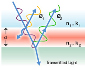
This measurement technique is based on the reflectance of light. Some incident light will reflect off of the PVDF-TrFE film, while some light will transmit through the film and reflect off of the silicon substrate. Because of the path length difference, the light will create an interference pattern. By using the known refractive index of PVDF-TrFE, this pattern can be analyzed to determine the film thickness.
All films were measured using this technique. The results showed that films made using the LB technique did not have reliable and predictable thicknesses. Likewise, several of the spin-cast films were shown to be inconsistent. This technique aided in understanding the results of the x-ray diffraction experiments.
 LB film thickness characterization |  Spin Time vs Film Thickness |  Spin Speed vs Film Thickness |
|---|
Results of the film thickness measurements are shown on plots correlated with the number of layers (for LB) and the spin time and speed (for spin-cast).
Figure 1: Illustration of light interference in a thin film


Images of PVDF 4 (100 layers)
These images show regions of very dense PVDF-TrFE with regions of bare Si, confirming that this is not a coherent film, and it is not a useable sample.
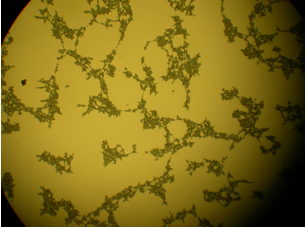
Images of RAPVDF2
These images also show regions of bare Si within the film. It appears as if the polymer precipitated during the spin- casting.
Images of RAPVDF5
Although this film did not fit the light reflectance models as well as others, this image confirms that it is a continuous film. The image shows a region in which we scraped off the film on the bottom left. It is clear that the film in the top right region is continuous and consistent.
Optical Microscopy
Because the results of the film thickness measurement raised some suspicion about certain samples, we decided to examine the films with an optical microscope